
Hydraulic Fracturing
Gas Drilling – Impacts on Water Quality
“Stop the debate and let the data do the talking.”
YSI’s environmental monitoring systems can operate 24/7 to provide the “truth”--critical, real-time data on the conditions near hydrofracking sites. The systems can provide early warning for the accidental release of pollutants—or reassurance that water quality has not been affected.
For gas companies, drill operators, monitoring agencies, environmental consultants, or private citizens, it is critical to obtain high-resolution water quality data to provide an accurate picture of natural and unnatural changes in the area around the gas field.
Natural gas is quickly developing globally as an alternative to petroleum-based energy sources. The process of extracting gas from shale rock formations --called hydraulic fracturing or fracking--is also developing rapidly. Current extraction methods require large quantities of water from natural sources, and the various steps of the process may pose threats to human and environmental health if not controlled and monitored effectively.
| Marcellus Shale Info Clearinghouse -- Institute for Energy and Environmental Research |
Marcellus Shale-- Penn State Cooperative Extension |
Hydraulic Fracturing Overview and Groundwater -- US EPA |
Leakwise systems, which consist of one or more sensors and controllers, can reliably detect, monitor, measure, send alerts, and activate controls when detecting hydrocarbons on water.
The Leakwise product line provides breakthrough electromagnetic absorption technology for the early detection and monitoring of hydrocarbons on water. Growing environmental concerns about our global water resources make Leakwise oil-on-water measurement systems critical for detecting and mitigating water pollution events. Oil refineries, seaport authorities, water municipalities and power generation facilities are a few of the industries benefiting from Leakwise technology.
Capabilities
Leakwise oil spill detection and monitoring systems feature reliable, worry-free 24/7 monitoring, and require almost no maintenance. Leakwise can:
The Leakwise product family includes:
| Product | Application |
|---|---|
| ID-221 Oil Sheen Monitoring System | Hydrocarbon on water detector for sumps (wet), tanks, ponds, and groundwater wells |
| ID-223 Oil Sheen Monitoring System | Hydrocarbon on water detector for sumps (wet and dry), ponds, and canals |
| ID-225 Oil Thickness Monitoring System | Hydrocarbon layer thickness monitor for oil/water separators, groundwater wells, sumps (wet), tanks, and ponds |
| ID-227 Oil Sheen Monitoring System for Marine Applications | Hydrocarbon on water wave rider detector for marine offshore applications, lagoons, lakes, rivers, open canals, and large retention ponds |
![]()
INTRODUCTION
Storage tanks containing hydrocarbon feedstocks, intermediates and finished products will, over time, accumulate a water layer in the bottom of the tank (exceptions are water-soluble hydrocarbons such as alcohols and ethers). Standard industry practice is to periodically drain the water from storage tanks so that the water does not adversely impact specifications of the hydrocarbon. Water removal also reduces corrosion problems on the floor of the tank and the risk of "Boil-Overs" in case of fire.
Manual control of water draw-off can result in HC product in the discharge. The loss of this HC product means less product available for sale and increases the cost of wastewater treatment. Additionally, environmental regulation trends (e.g., USA Benzene/NESHAP and SOCMI/HON) may impose large economic penalties for designing water draw conveyance and treatment systems that allow HC product in the water draw-off discharge.
Two types of water draw-off control approaches use the AGAR ID-200 Series Interface Detector. Each water draw discharge control strategy has its own advantages and disadvantages.
The control strategies are:
Using In-Tank Interface/Concentration Detectors
Using Insertion Hydrocarbon/Water Monitors in the Effluent Water Draw-Off Line
AGAR applications specialists can assist in identifying the optimum strategy for controlling water discharge.
I. IN-TANK INTERFACE DETECTOR
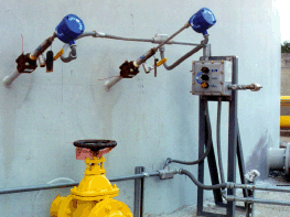
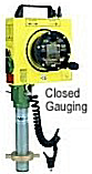
In-Tank measurement of the hydrocarbon/water interface gives the best results for eliminating the discharge of hydrocarbons. Usually, AGAR ID-201 probes are inserted into the tank through AGAR's patented seal housing, as shown in the photo above. Special installation may require the use of the AGAR ID-202 for extended length.
The two probe system can operate under two strategies. A main control/safety strategy - System #1 shown in Figure 1 and a high-low control strategy - System #2 shown in Figure 2.
System #1
When the AGAR ID-201 probe detects HC free water, the water discharge valve is opened. As water is drained off the bottom of the tank, the hydrocarbon/water interface begins to drop. When the AGAR ID-201 probe detects the hydrocarbon/water interface, the signal is sent to close the discharge valve. Output options to control the valve can be 4-20 mA, relay and/or pneumatic. Local indicating lights are also available. If the hydrocarbon floats, the ID-201 will prevent it from being discharged with the waste water.
Figure 1 shows an upper probe used for control, with the lower probe used for low-level alarm and positive shutdown of the water discharge valve.

Figure 1
|
||||||||||||||||||||
System #2
Figure 2 shows the high-low control logic in which the valve would close only after both probes have detected hydrocarbon. Figures 1 and 2 also show how to overcome tank bottom sludge build-up problems by placing the active part of the AGAR ID-201 probe over the sump in the bottom of the tank. It is nearly impossible for sludge to build-up and cover the probes in this configuration.
Figure 2
|
||||||||||||||||||||||||||||||||||||||||||||||||||||||
II. IN-LINE HYDROCARBON/WATER MONITORS
The advantage of this approach is the avoidance of tank penetration, elimination of bottom sediment build-up, and the elimination of the free water in the tank.
However, there are significant disadvantages that should be considered in design and policy decisions:
Figure 3 shows how the conventional Vortex Breaker bent pipe traps hydrocarbon at the end of the water draw-off cycle.
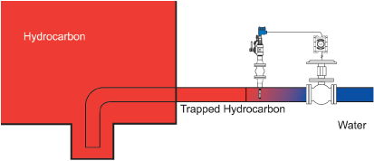
Figure 3
Assume a case where the hydrocarbon and the water have completely "phase separated" to form a clear-cut interface inside the tank. Because hydrocarbon is still present from previous water-draw, the water draw cycle will have to be initiated manually. Water will have to displace the HC before the probe can be activated. Once this has occurred, water will continue to drain until the oil/water monitor again detects hydrocarbons. At this point, the oil/water monitor will send a control signal that is used to close the water draw-off valve. However, due to the bent pipe design, this hydrocarbon is again trapped in the draw-off line. As water gradually builds up in the tank, the hydrocarbon trapped in the line acts as a seal (being lighter than water). To re-activate the dump valve for a new water-draw cycle, the oil/water monitor signal must be overridden to flush the hydrocarbon out of the line before water is again detected. Some HC is discharged to the waste water treatment system during every dump cycle.
Figure 4
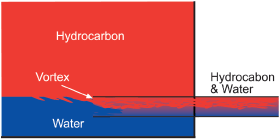
There is no assurance there will be sufficient water in the tank to flush all hydrocarbon out of the water draw-off line. Thus, the pipe must be designed in such a way as to eliminate the trapping of hydrocarbon. A small upward inclination is desirable, with a vortex breaker at the intake. The latter avoids vortexing and the suction of hydrocarbon with water when the dump valve is fully open. Figure 4 shows hydrocarbon being discharged with the water because of the vortex action.
Figure 5 shows the correct installation with a slotted discharge pipe. Note, the cross-section of the slot must be at least ten times larger than the cross-section of the pipe. Similarly, the pipe can be perforated with many holes, whose total crosssection area exceeds the pipe's area by a factor of ten.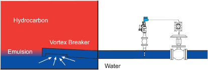
If the hydrocarbon is highly viscous, special care must be taken to compensate for hydrocarbon fouling that will stick to pipe walls and the AGAR oil/water monitor. The amount of hydrocarbons discharged will depend on the oil's viscosity and the flushing action of the effluent water. Calibration adjustments to the oil/water monitor will negate the effects of fouling.
Figure 5
NOTE: Also available in a 2-wire, 24VDC loop-powered system

MMC International Corporation primarily manufactures equipment and instrumentation for use in the hazardous or potentially hazardous environments found aboard petroleum and chemical transport vessels. Its products are also used in petrochemical and pharmaceutical processing facilities. The firm maintains sales and service offices in North America, Europe, Asia and Australia.
The enterprise that became MMC started in the early 1940s as the Marine Plastics Corporation, making deck surfacing for tankers and military vessels. After the close of World War II, the name was changed to the Marine Moisture Control Company to reflect the firm's rapid expansion as a manufacturer of equipment for the removal of moisture from shipboard machinery and cargo spaces. Over the next several decades, MMC moisture control devices--such as its corrosion-preventing gear case dehydrators--became standard components throughout the world's fleets of tankers and dry cargo vessels.
 The MMC product line continued to expand with lube oil clarifier coalescers, hydraulic valve systems, draft-indicating and tank-gauging systems, cargo-handling hose couplings, and other crucial items required by petroleum and chemical transport vessels.
In 1972, MMC pioneered solid-state electronic gauging equipment for use in hazardous shipboard environments. That new line of equipment was designed to meet the emerging international standards of explosion-proof or flameproof safety in the petroleum and chemical transport fields. Today, this category of highly specialized safety gear is referred to internationally as "Intrinsically Safe Equipment" and MMC remains a state-of-the-art leader in the field it helped invent. Since the 1970s, MMC's Intrinsically Safe Equipment products have been approved by international certifying agencies such as Factory Mutual, CSA, SAA, EECS, NKK, NK (Japan) and HK.
By the 1980s, MMC's product line had grown to include mechanical, electro-mechanical and electronic monitoring and safety equipment used by industrial facilities involved in the transport, storage and processing of a wide variety of chemicals. In addition, the firm's technology was adapted for environmental monitoring purposes, spawning yet another new product line beyond the maritime field.
Thus, by 1990, the company changed its name to MMC International Corporation to more accurately reflect the diversity of its product lines, the broad base of its technological research goals, and the global reach of its sale 
 |
 |
 |
 |
Click on any item above for equipment specifications pages.